Stage 2: Preliminary Design

Welcome to the Purdue OWL
This page is brought to you by the OWL at Purdue University. When printing this page, you must include the entire legal notice.
Copyright ©1995-2018 by The Writing Lab & The OWL at Purdue and Purdue University. All rights reserved. This material may not be published, reproduced, broadcast, rewritten, or redistributed without permission. Use of this site constitutes acceptance of our terms and conditions of fair use.
Once the design concepts have been developed and a final concept has been selected, the next stage in the design process is to develop the preliminary design of each of the system components. The key elements of most preliminary designs include an outline of the following items: the design’s systems, its basic requirements, and the high-level design features.
For our UAV example, we would start by creating a flowchart (or similar schematic) of the various systems, subsystems, and components of the UAV. For example, let’s say that we want to create a schematic of the flight system. Assuming we choose the quadcopter concept design, our top-level “block” in the flowchart would say “flight system.” Then, we would subdivide this system into its constituent subsystems, namely, each of the four rotor assemblies. These rotor assemblies consist of individual components, including the rotor blades, motors, wiring, and possibly the electronic speed controllers (ESCs). The motors and ESCs each have dozens of internal components, and the level of representation of these components is dependent on the requirements that must be levied on the system.
For example, if the motors are designed in-house, it may make sense to further subdivide the motor into flowchart blocks that highlight its major components, as their design requirements may be tighter due to the ability to control each minute specification. However, if the motor is sourced from an external supplier, then the level of subdivision may be more coarse—i.e., limited to the options that can be specified when ordering from the supplier. The figure below shows an example of a preliminary design flowchart for our quadcopter’s flight system.
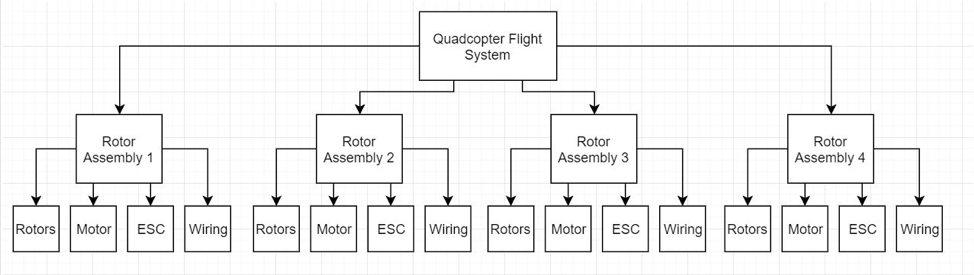
Quadcopter preliminary design flowchart
After creating flowcharts for each UAV system, the next step is to clearly define the system, subsystem, and component requirements. These requirements are often determined after consulting with the end users and developing mission use-cases. For example, let’s say that the farmers using the UAV want to be able to conduct at least 500-acre aerial sweeps in a single charge. In this case, the quadcopter must be able to aerodynamically support the weight of its components plus the imaging equipment while navigating the field area. It must also be capable of supplying adequate power to the imaging equipment and flight systems while accounting for the extra power demanded by anomalous factors such as wind gusts or changes in altitude to accommodate low or high-level imaging.
The design features of each system are usually defined quantitatively, so high-level aerodynamic, structural, and electrical analyses should be carried out to obtain approximate numbers for each of the systems and subsystems. The minute details of each component and system will be defined later in the detailed design phase. Once the features are defined, they are analyzed to ensure that they meet the pre-specified design requirements. The text below shows a sample of what the requirements and design features of the quadcopter flight system might look like:
Requirements: The quadcopter’s flight system must be capable of supporting 32 kg throughout the entire flight envelope. Nominal operating altitude will top out at 30 meters above ground level. The quadcopter must be capable of at least 10 m/s horizontal speed and at least 5 m/s vertical speed while overcoming vertical wind gusts of up to 2 m/s…
Design features: The quadcopter rotors will consist of three blades with airfoils characterized by a high L/D ratio. The rotors will be fabricated out of glass fiber composite material. The motors will be brushless and powered by a Lithium-ion battery…
Note that this stage of the design process becomes an increasingly iterative process. This means that once a system’s preliminary design is completed, it should be reviewed and modified in order to generate a new design. This looped process saves time and resources by considering the effects of a particular system architecture and incorporating changes at the early stages of the design. Therefore, the preliminary design documentation may also include simulation and requirement verification reports that highlight the necessary design changes prior to developing the detailed designs of each system and component.
For example, let’s say that the quadcopter rotors are initially designed to have three blades. However, a preliminary aerodynamic analysis of the rotors suggests that at least four blades will be necessary to generate enough lift to overcome the stipulated minimum wind gust requirement of 2 m/s. The best course of action is therefore to create a report that includes the quantitative results of this mission architecture simulation and a list of the requirements that were both met and not met. Finally, the necessary architecture/design changes should be clearly enumerated.
To summarize, the preliminary design document consists of the following elements:
- Flowchart (or other schematic) of each system
- Clear definition of each system’s, subsystem’s, and component’s requirements
- High-level outline of design features that meet each of these requirements
- Requirement and system architecture verification reports