Stage 4: Manufacturing and Next Steps

Welcome to the Purdue OWL
This page is brought to you by the OWL at Purdue University. When printing this page, you must include the entire legal notice.
Copyright ©1995-2018 by The Writing Lab & The OWL at Purdue and Purdue University. All rights reserved. This material may not be published, reproduced, broadcast, rewritten, or redistributed without permission. Use of this site constitutes acceptance of our terms and conditions of fair use.
Once an engineering design has been finalized, the next critical step is to successfully translate these designs into concrete and replicable manufacturing processes. As mentioned in the previous stage, a designer will hopefully have clearly specified manufacturing tolerances on all 2D drawings of assemblies and parts. However, merely specifying manufacturing tolerances is not enough to ensure that a specific component can be manufactured appropriately. Therefore, there are several important types of documents that must be created to ensure reliable and efficient manufacturing standards.
Many technical organizations, such as ASTM (American Society for Testing and Materials), publish and update documents that specify key manufacturing standards. These documents range from fastener standards that specify fastener coating types, grip lengths, and materials, to standards that determine acceptable procedures for handling raw metal processing. Additionally, customer-specific standards also exist, with one very common example being the United States’ Department of Defense Military Standards.These standards were originally designed to provide guidelines to manufacturers who intend to create products for the military. However, many non-defense manufacturers have adopted many of these “MilSpec” guidelines due to their comprehensive nature and thorough attention to detail. Depending on the specific engineering firm designing a given product, the specific standards used during manufacturing are often pre-determined and available for reference on-site immediately. However, any novel manufacturing methods may need to be audited, and new standards may need to be cross-referenced to ensure the robustness of the manufacturing techniques being employed.
Another key aspect of the manufacturing process is accurate documentation of manufacturing tooling and interfaces between tooling and components that are being fabricated. Tooling encompasses manufacturing aspects that include (but are not limited to) fixtures to hold components or assemblies in place, molds for specific components, and cutting or metal stamping patterns. For a given product, the engineering specifications for these fixtures, molds, etc. will be specific to the components being fabricated and joined together in assemblies. Therefore, manufacturing tooling specification documents must be created. In our quadcopter example, the rotor assembly’s constituent parts, such as the rotors, may require the blades of the rotor to be individually molded out of plastic and then joined to the central hub. Alternatively, the entire rotor may be created out of a single mold. Regardless of the specific fabrication technique employed, precise work instructions must be written in such a manner that technicians can systematically create robust components that meet the engineering criteria laid out in previous stages of the design process.
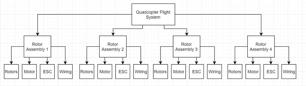
When joining components together in assemblies, a specific list of work instructions may be necessary to provide technicians with assembly steps and tolerance requirements. For example, if we were to assemble the rotors, motors, ESC, and wires that make up the rotor assemblies from our quadcopter preliminary design flowchart, the assembly instructions (and a notional assembly diagram) might look like this:
- Place motor housing into assembly jig. Ensure that the shaft is aligned perpendicular to the assembly surface and the housing is seated properly in the jig.
- Align the rotor hub with the motor shaft. Ensure that the rotor is oriented as shown in the assembly diagram.
- Move the rotor down until the attachment hole lines up with those in the motor shaft.
- Place the attachment bolt through the shaft and rotor mast.
- Torque the bolt per the specification listed in the assembly diagram.
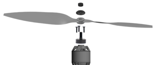
Notional rotor assembly diagram
In many manufacturing scenarios, human assembly may be supplanted by automated assembly lines, so natural-language instructions will need to be translated into code. Subsequently, this code will need to be documented well and tested periodically to ensure that the assembly process runs smoothly. In order to verify the quality of products being assembled, random quality control inspections may be required. These inspections will often have their own set of pre-determined procedures that must be clearly enumerated and understandable by quality control engineers or technicians. For example, the bolts that join the rotor to the motor hub may need to be checked for tightness and re-torqued prior to subsequent testing of the rotor assembly to ensure that the rotor will not fall off during flight.
Inevitably during the manufacturing process, problems will arise. These may include issues with part accessibility by technicians during assembly, a disconnect between the engineering design intent and the corresponding manufactured parts or assemblies, or even issues with parts not being able to withstand applied loads. For this reason, technicians will likely generate Engineering Change Requests (ECRs) that are passed on to manufacturing engineers. These ECRS can range from short blurbs in the electronic submission system that highlight simple issues like improper fastener grip lengths to longer, formalized reports that request more complicated engineering design changes that may impact production output at a larger scale. Manufacturing engineers will therefore have to not only manage the edits to engineering documentation associated with a part or assembly that needs to be changed, but they will also need to document their changes in the ECR submission system.
To summarize, the manufacturing phase consists of the following documentation:
- Manufacturing standards
- Tooling specification documents
- Component/assembly fabrication steps
- Quality control documents
- Engineering change requests