Stage 3: Detailed Design

Welcome to the Purdue OWL
This page is brought to you by the OWL at Purdue University. When printing this page, you must include the entire legal notice.
Copyright ©1995-2018 by The Writing Lab & The OWL at Purdue and Purdue University. All rights reserved. This material may not be published, reproduced, broadcast, rewritten, or redistributed without permission. Use of this site constitutes acceptance of our terms and conditions of fair use.
After developing the preliminary designs and requirements of each system, the next step is to create the actual designs of each component. Detailed engineering design drafting and analysis will take place during this stage of the project, which will require a plethora of documentation. Care must be taken to make sure that no aspect of the design is missed and that all relevant engineering info about each system’s design is clearly documented, as the information and documentation from this stage will directly impact the manufacturing process.
Although CAD drawings have been generated in the conceptual phase, these drawings are very high-level in nature and thus primarily serve to ease the process of selecting an overarching design concept. As a result, a majority of the systems and subsystems are likely not modeled. Therefore, their specific designs must be addressed in this phase.
For example, a comprehensive CAD representation of our quadcopter subsystems may include separate models of the propellers, structural members such as the landing legs and central support frame, motors, and more. Once each individual system, subsystem, and component is modeled, an assembly model is developed in CAD. This model is an amalgamation of all the individual systems’ CAD models, and its essential function is to illustrate the positioning of all the components within the final assembled quadcopter design. To this end, the assembly model will likely include details such as the exact positioning of components relative to each other, wiring layouts, and even the locations and types of fasteners used to join the components together. Note that separate system-level assembly models may be created and later joined into a final overarching assembly model.
Of course, manufacturing is never a perfect process, even with the state-of-the-art automated assembly and fabrication equipment available to engineering firms today. Therefore, it is critical for the designers to specify engineering tolerances on both the component designs in the individual CAD models and the dimensions in the assembly model. When handing off the CAD models or 2D drawings to the manufacturing staff, designers should carefully list the desired component dimensions along with reasonable tolerance margins to allow for slight imperfections in the manufacturing process.
Detailed mathematical models are also generated during this design phase. These models span all pertinent systems/subsystems in the design, as CAD representations are not sufficient to communicate the full design intent. Furthermore, these models are crucial to understanding the design’s integrity during all anticipated “nominal” conditions and a range of atypical conditions. For example, detailed aerodynamic and structural models of our quadcopter’s propellers may be necessary to ensure that they are operating in most efficient way possible (low drag, high lift) and are able to withstand sudden gusts of air, respectively. After these models are created for all relevant systems/subsystems, detailed documents of the results from simulations/analyses that utilize these models should be generated.
These documents could potentially include the following elements:
- A high-level explanation of the mathematical model and its rationale.
- Detailed explanation of the model. This will likely include the governing equations, input parameters, and modeling tool used (most often, this is a software package or custom-written code).
- Explanation of how the modeling/analysis tool was run.
- Summary of results from the analysis.
Although code is not typically thought of as a document, it actually is! Modeling/analysis code must be commented and laid out well. Clear commenting serves multiple purposes, such as allowing members of a multidisciplinary design team to more easily follow the work of the author(s) of the code and successfully run it. Furthermore, neatly organized and well-commented code allows for easier reproduction of results and modification of portions of the code to accommodate different iterations of the design. The figure below shows an example of a well-documented structural analysis MATLAB script. Note how the sections for data input, calculations, and plotting are all separated into discrete sections, and each section has comments that explain the function of each relevant line of code.
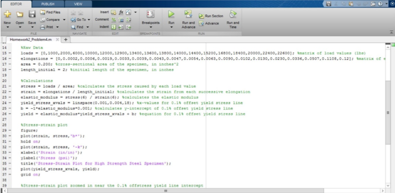
An example of structural analysis code
Often, one unifying design document can be created either for the entire product or at the level of individual systems. Some examples of these include an airframe structural design document, electrical system design document and an aerodynamic design document. For example, a quadcopter airframe structural design document might outline the structural analyses carried out on each landing leg, rotor mounting points, central quadcopter frame, and other structural members. Since each department produces different design documents, it is important to keep as unified a documentation standard as possible to allow for better cross-communication of design intent. A unifying design document therefore would likely consist of separate sections for each engineering department and an explanation of how the designs connect or their implications on each other in the overall design.
To summarize, the detailed design phase consists of the following documentation:
- Detailed CAD drawings of each component/subsystem (with tolerances for manufacturing)
- Assembly CAD drawings of each system/the entire design (with tolerances for manufacturing)
- Mathematical models and related documentation
- Well laid-out and commented analysis/modeling code
- System-level design documents and potentially a design-level unifying design document